- Remove Cluster
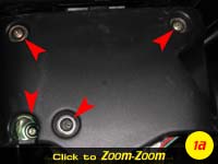
- Remove 2 screws on Kick Panel below the steering column
- (see picture 1a) - Remove the 4 screws
that hold the steering column/lock cylinder cover in place
- Remove the 2 screws in the bottom of the cluster shroud
- (see picture 1b) - Remove the 4 screws
that hold the cluster in
- (see picture 1c) - Unhook the 2 large
wiring harnesses on the back of the cluster
- Unhook small wiring harness on the back of the cluster (For the
rear defroster indicator light, left hand side of cluster as normally
look at it)
- (see picture 1c) - Unhook the
speedometer cable (push down on the raised bar on the top of the
connector while pulling out gently on the cluster)
- Take the cluster to the workbench
|

 |
- Disassemble the Cluster
- CAUTION - Do not touch the gauge faces, fingerprint oils will not
come off! (I've do it and cleaned them with water,b ut the color of
the face looks different afterwards)
- CAUTION - Do not remove the needles, or bump them. You don't need
to mess with the needles at all for this modification.
- CAUTION - Don't let anything get inside the clear plastic cover
once it is removed. Don't touch the inside of it. Don't scratch it!
- Remove the clear plastic cover
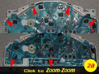
- (see picture 2a) - Press in the black
tabs while gently pulling out on the clear assembly. Start at one
end, applying pressure while pushing them in, and it should work
fine.
- If you are having trouble with it clicking itself back together
as you go around, stick a small screwdriver in between the cluster
and the clear piece as you work your way around, careful not to hit
the faces/needles.
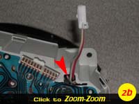
- (see picture 2b) - Make sure the rear
defroster indicator light wiring harness comes out through the hole
in the casing, you will probably have to pull the circuit trace part
back a little to feed it through the hole. Bending it won't hurt the
traces, so move it as needed. Make a note of how it was routed so it
is reassembled the same.
|
 |
- Remove the Temperature Gauge Assembly
- (see picture 3a) - Remove the 3 screws
on the back side that are holding the gauge in. The gauge may fall
out, so be mindful of it coming loose.
- Pull gauge out the front of the cluster, set cluster aside (make
sure the faces don't get touched!)
|
|
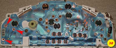
- Modify the Temperature Gauge
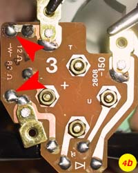
- (see picture 4a) - Remove the 82 ohm
resistor
- (see picture 4b) - Heat the solder on
the back
- Suck/wick hot solder away
- Bend legs over on resistor so it will pull out
- Pull out resistor from front side
|
|
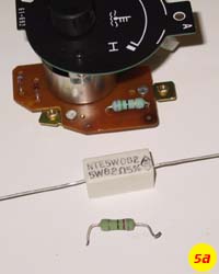
- (see picture 5a) - Install the 82 ohm, 5
watt resistor
- Bend legs over on the new resitor
- Insert legs into holes from the top side. Make sure to leave it up
off the board so it isn't touching anything and air can get around it
on all sides.
- Bend over ends of tails on back side
- Solder points on the board on the back side
- Nip off the tails of the wires you just soldered
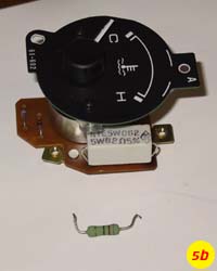
- (see picture 5b) - Bend the resistor as
needed to maintain air gap on all sides.
|
|
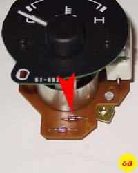
- (see picture 6a) - Remove the Zener Diode
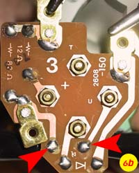
- (see picture 6b) - Heat the solder on
the back
- Suck/wick hot solder away
- Bend legs over on zener diode so it will pull out
- Pull out zener diode from front side
|
|
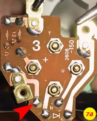
- (see picture 7a) - Using the drill and a
very small bit, enlarge the power side hole of where the Zener Diode was
|
|
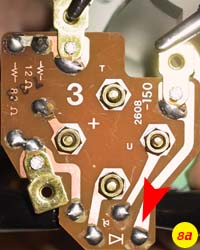
- (see picture 8a) - Drill small hole in
ground trace, just above existing diode solder location
|
|
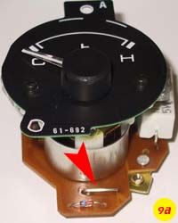
- (see picture 9a) - Install a piece of the
wire in place of the Zener diode
- Bend ends over at 90 degree angles
- Insert in holes from the front side
- Bend over on back side to secure it against board
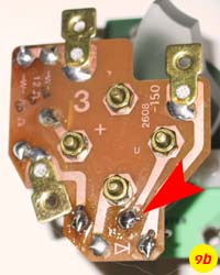
- (see picture 9b) - Solder ONLY the stock
hole, not the enlarged one
- Nip off tail from the wire you just soldered
|
|
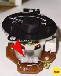
- (see picture 10a) - Install the parallel resistor
- Bend legs over
- Insert in holes (one end in the ground hole you drilled, the other
in with the jumper hole you enlarged.
- Bend over ends, making sure it is sitting high up off the board
and not touching anything.
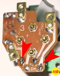
- (see picture 10b) - Solder both ends
- Nip off all tails from ends you just soldered
|
|
- Reassemble the Cluster
- Put gauge back in, aligning posts with holes in gauge face
- Verify that the large 82 ohm resistor isn't touching anything in
the cluster
- (see picture 3a) - Put in the 3 screws
on the back
- (see picture 2a) - Put the clear plastic
cover back on, snapping it in place all the way around.
- (see picture 2b) - Make sure to feed the
wiring harness into the hole in the casing, and route it as it was
before.
|
see picture 3a above
see picture 2a above
see picture 2b above |
- Install Series resistor in line to
Thermistor
- (see picture 12a) - Locate right wiring
harness
- (see picture 12b) - Locate far right
wire (black with blue strip on my 97) and cut wire leaving tails long
enough to solder to and get heat shrink around
- (see picture 12c) - Solder Series resistor between to ends of the wire
- Do NOT heat shrink/tape yet
|


 |
- Calibrate/Reference the Gauge
- (see picture 13a) - Install "COLD"
calibration resistor from after the 16 ohm resistor ( opposite side of
resistor from harness) to chassis ground
- Test fit the cluster, connecting the right hand wiring harness
(the one you just soldered on)
- Turn car on (do not start)
- Gauge should read "C" (the first mark on the left)
- If it reads nothing, pegged to the right or a long way off from
"C", remove cluster, disassemble and check gauge connections
starting at step 9a
- If it reads "C", switch "COLD" calibration resistor to "HOT"
calibration resistor.
- Gauge should read "H" (the last mark on the right)
- If it reads nothing, pegged to the right or a long way off from
"C", remove cluster, disassemble and check gauge connections
starting at step 9a
- If it reads "H", then you did it all right!
- Remove Cluster
- Remove calibration resistor
- Heatshrink/wrap with electrical tape the entire assembly from
solder to solder so no metal is exposed
|

|
- Reinstall the cluster in the car
- (see picture 1c) - Insert Cluster into
opening, aligning the speedometer cable assembly.
- Click speedometer cable onto cluster
- (see picture 1c) - Connect 3 wiring
harnesses on the back of the cluster
- (see picture 1b) - Install 4 screws
holding the cluster in
- Snap shroud back on over cluster. Make sure to put it in straight
so as to not snap off the guide pins.
- Install 2 screws in bottom of shroud
- Reassemble the column/lock cylinder cover pieces
- (see picture 1a) - Install 4 screws
holding cover in place
- Install kick panel and 2 screws
|
see picture 1c above
see picture 1b above
see picture 1c above |
- Test Gauge
- Turn ignition to "on", the gauge may move a very small amount
(maybe 1/16" of an inch, it shouldn't rise above "C")
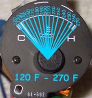
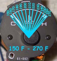
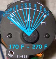
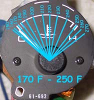
- Drive car until it warms up to normal operating temperature. The
needle should indicate somewhere between the 12 o'clock and 1 o'clock
positions.
|
|


